
![]()
(Ultimo aggiornamento:
04/09/05)![]()
Progettazione e realizzazione di un aquilone
Negli ultimi tempi, costruire un aquilone è un'arte esclusiva di un piccolo gruppo di persone che sono dotate di grandi conoscenza aerodinamiche, abilità nel disegno, nel cucire e altre abilità manuali.
Non più! Con l'aiuto di moderni programmi software per progettare aquiloni, database di airfoils, esempi di progetto di aquiloni e aiuti esterni per le cuciture, quasi tutti i kiters possono farsi il loro aquilone costruito su misura. Lasciateci guardare questi elementi uno ad uno per vedere dove siamo arrivati con l'arte di costruirsi il proprio aquilone:
-
Raccolta dati di progetto di esempio della Kitesurfingschool.org
-
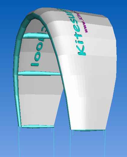
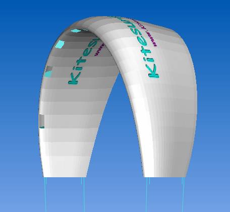
Teoria LEI (leading edge inflatable = gommone)
Gli aquiloni sono dispositivi aerodinamici veramente complessi (complessi quanto un'ala di aereo se non di più). Se non avete confidenza con termini come airfoil, profilo, ala e altra terminologia associata, leggete http://www.dreesecode.com/other/aflprimer.pdf o altre premesse sugli prima di continuare.
I parametri più facili da maneggiare e altamente visibili sono l'Aspect Ratio (AR), l'Airfoil Profile e l'Angolo di attacco (AoA) dell'aquilone:
Aspect Ratio
-
Aspect Ratio è approssimativamente l'Larghezza/Corda dell'aquilone o più precisamente Larghezza*Larghezza/Area. Finchè lo AR determinerà la forma dell'aquilone questo saràl'aspetto più visibile da parte dell'utilizzatore. Aquiloni con alto AR hanno meno trascinamento indotto (up-wash e effetto vortice sui tip) rispetto ad aquiloni con le stesse caratteristiche ma basso AR. Il trascinamento indotto è inversamente proporzionale allo AR. Quando sono stazionari nella finestra del vento, un aquilone con basso AR può generare la stessa quantità di trazione di uno con alto AR (con le stesse caratteristiche) ma come abbiamo bisogno di muovere l'aquilone (per saltare o in condizioni di scarsa potenza), un aquilone con alto AR può accelerare più velocemente e quindi prendere potenza più velocemente di un aquilone con basso AR. Come regola generale, un alto AR indica una finestra di potenza più grande (la differenza tra la minima e la massima potenza) a un basso AR una più piccola. Di seguito si riportano i valori di AR consigliati:
Aquilone
AR molto basso AR basso AR moderato AR alto AR molto alto Foil 2.5- 3 4 5 5.5+ Gonfiabile / Arc 3- 4 5 6 7+ I gonfiabili e l'Arc hanno una sagoma sferica, una forma naturale stabile, il loro AR è normalmente più alto di quello di un foil.
Profilo di Airfoil
-
Airfoil da sollevamento e trascinamento. Un profilo con alto sollevamento quando stazionario alla finestra del vento da la massima trazione (AoA circa 5 gradi). Un profilo con più alto rapporto sollevamenbto trascinamento accelererà più velocemente e genererà più potenza quando volerà attraverso la zona di potenza della finestra del vento. Un airfoil con grande lift è talvolta etichettato come "trattore" perchè tira come un trattore quando nella finestra del vento. Un aquilone con alto rapporto sollevamento/trascinamento è etichettato come airfoil "veloce" perchè vola molto veloce nella zona di potenza generando una tremenda potenza. Un airfoil "veloce" può generare molta potenza nella finestra del vento ma non necessariamente quanta ne genera un "trattore". La tabella successiva mostra il raccomandato sollevamento e rapporto sollevamento/trascinamento:
Molto basso Basso Moderato Alto Molto alto Coefficiente di sollevamento (at AoA = 5) < 0.5 0.7 0.9 1 > 1.1 (trattore) Rapporto Sollevamento/trascinamento < 50 70 90 100 > 110 (veloce) E' meglio usare un programma di progettazione di airfoil (come DesignFoil su http://www.dreesecode.com/ - se volete comprare il software dopo aver esaurito il periodo di prova, potete ottenere uno sconto con la licenza educazionale menzionando che siete un lettore della kitesurfingschool.org) per progettare, analizzare e selezionare il profilo di aquilone da usare per il vostro airfoil (ai fini del kiting, in numero di Reynolds va da 1.000.000 a 2.000.000).
Alcuni progettisti di aquiloni si vergognano della complessità del progetto, dell'analisi e dell'uso delle regole comuni e dei metodi di cambiare lo spessore del profilo per cambiarne le caratteristiche di sollevamento ed il rapporto sollevamento/trascinamento. Questo metodo non è accurato ma per un aquilonista può essere accettabile. A regola di bazzi'a, aumentare lo spessore del profilo per aumentare il sollevamento alla finestra del vento e diminuire lo spessore per aumentare la sua velocità. La tabella seguente mostra il campo degli spessori dei profili più usati per gli aquiloni:Profilo per Foil e Arc Profilo per Gommoni -
sottile (veloce): < 14%
-
moderato: 15%
-
spesso: 16%
-
molto spesso: 17%
-
il più spesso (trattore): 18% or more
-
sottile (veloce): 8% - 9%
-
moderato: 10%
-
spesso: 11%
-
molto spesso: 12%
-
il più spesso (trattore): 13% - 14%
-
AoA a tipico
-
Un aquilone ha più sollevamento con alto Angolo di Attacco (AoA) al vento (più superficie proiettata al vento e anche un AoA da 0 a 16°, il Coeficiente di sollevamento di un airfoil aumenta ad un valore ottimale). Ciascun aquilone ha un suo AoA tipico e "neutro" per il suo centro e per le sue estremità quando è in sopra la vostra testa al limite della finestra del vento (con le linee di potenza e dei freni della stessa lunghezza). L' AoA tipico, in condizioni quindi di riposo, va da 0 a 5 gradi. Occorre notare che a riposo l'aquilone vola a 85° di elevazione in modo che l'AoA del centro del profilo in volo è la somma dello AoA tipico e la differenza tra l'elevazione di volo dell'aquilone e la verticali (5 gradi ottenuti come 90 - 85°). Cambiando l'AoA tipico può cambiare la dimensione della finestra del vento tanto che le due possono "amplificare" ciascuna l'altra per avere un effetto di "doppio AoA". Per es. cambiando lo AoA tipico da 2 a 0 fa cambiare la finestra del vento da 85 a 84°; quindi l'AoA dell'aquilone in volo alla finestra del vento è 4° invece di 7.
E' interessante leggere i Miti di Peter Lynn 1 e 2 in cui egli inizia dicendo che il sollevamento o trazione dell'aquilone alla finestra del vento è proporzionale alla AoA tipica mentre il rapporto sollevamento/trascinamento è inversamente proporzionale. [sebbene l'aquilonista possa cambiare l'AoA dell'aquilone durante il volo cambiando la lunghezza delle linee frontali rispetto a quelle posteriori, comunque, questo in qualche modo deforma l'aquilone facendogli perdere alcune delle caratteristiche che si volevano raggiungere in sede di progetto. Un aquilone lavora meglio con un AoA intorno a quello di progetto]-
un aquilone con un basso AoA ha una finestra del vento maggiore ma può sovravolare (passarci sopra la testa,, oltre i 90°) e collassare facilmente senza avere molta trazione alla finestra del vento (un aquilone veloce dovrebbe avere un AoA basso, intorno a 0°). Questo tipo di aquilone deve avere un controllo istantaneo dell'AoA per prevenire collassi e anche per poter dare al kiter più potenza al bordo della finestra del vento.
-
un aquilone con un alto AoA ha una finestra del vento più piccola ma genera più trazione alla finestra del vento ed è più difficile che collassi (un trattore può avere unAoA da 3 a 5° per una maggiore trazione alla finestra del vento)
-
un aquilone tutto fare dovrebbe avere un AoA da 2 a 3°.
-
a causa dei fenomeni di up-wash e dei vortici all'estremità dell'ala, l'AoA delle estremità dell'ala può essere di 1 o 2 ° superiore dell' AoA a centro ala. L'effetto di wash-up riduce l' AoA all'estremità dell'ala, tale effetto può essere compensato progettando un aquilone con un AoA alle estremità più alto di 1 o 2° rispetto al centro.
-
per i gonfiabili e l' Arc, a causa della loro geometria, l'AoA all'estremità delle ali varia molto rispetto all'AoA del centro e quindi i due AoA sono progettati indipendentemente e il progettista deve aggiungere 1 o 2° al desiderato AoA per compensare l'effetto dei fenomeni di up-wash e dei vortici all'estremità dell'ala.
-
AoA molto basso AoA basso AoA moderato AoA alto AoA molto alto Campo (in gradi) < 0 1 2 - 3 4 > 5 Tipo di aquilone corsa velocità tutto fare onde trattore (Wake Style)
La tabella seguente fornisce il sommario dei parametri della AR, Airfoil, AoA:
| Basso | Alto | |
| AR | piccola finestra di potenza | grande finestra di potenza |
| sollevamento (alla finestra del vento) | perdite di trazione alla finestra del vento | forte trazione alla finestra del vento |
| rapporto sollevamento/trascinamento | lento | veloce |
| AoA tipica a riposo | grande finestra del vento piccolo AoA alla finestra del vento (meno trazione) collassa facilmente veloce |
piccola finestra del vento alto AoA alla finestra del vento (maggiore trazione) difficile da collassare lento |
ed il loro uso in differenti tipi di aquilone:
|
Tipo aquilone/vento |
vento leggero |
vento moderato |
vento forte |
| Gonfiabili (Foil) | 16 m2 (10 m2) e oltre | 8 - 16 m2 (5 - 10 m2) | 8 m2 (5 m2) e più piccoli |
| Scuola (stabile, basso sollevamento, lento) | moderato AR buon sollevamento buon sollevamento/trascinamento moderato AoA |
basso AR basso Lift moderato - basso sollevamento/trascinamento basso AoA |
molto basso AR molto basso Lift molto basso sollevamento/trascinamento moderato - basso AoA |
| Trattore (Wake Style, onde, vento a raffica) | moderato AR elevato sollevamento buon sollevamento/trascinamento alto AoA |
moderato - basso AR buon sollevamento moderato Lift/trascinamento alto - molto alto AoA |
basso AR moderato Lift basso sollevamento/trascinamento moderato - High AoA |
| Tutto fare | alto AR buon sollevamento elevato sollevamento/trascinamento alto AoA |
moderato AR moderato Lift alto - moderato sollevamento/trascinamento basso AoA |
moderato - basso AR basso sollevamento moderato - basso sollevamento/trascinamento moderato AoA |
| Velocità (salti alti, Freestyle) | elevato AR buon sollevamento elevato sollevamento/trascinamento moderato - basso AoA |
alto AR moderato Lift buon sollevamento/trascinamento basso - molto basso AoA |
moderato AR basso sollevamento moderato - basso sollevamento/trascinamento basso AoA |
Altri fondamenti sulla progettazione
-
il centro del profilo va selezionato per un ottimale sollevamento e per un ottimo rapporto sollevamento/trascinamento (ottimo in accordo con la tabell aprecedente sull abase delle caratteristiche richieste all'aquilone da progettare)
-
il profilo dell eestremità dell'ala va selezionato per la massima resistenza al collasso dell'ala (es. profilo reflex)
-
per i gonfiabili o per l'Arc:
-
questi aquiloni hanno la "stessa" superficie proiettata del 63% (2/p o 2/3.14159) della superficie della vela rispetto a qualsiasi altro parametro dell'aquilone (AR, rapporto bordo/centro corda, ecc.)
-
se le estremità dell'ala sono abbastanza grandi (il punto di rimorchio effettivo delle linee posteriori è più grande dell'80% della corda centrale), si può fare il rilancio all'indietro dell'aquilone tirando sulle linee posteriori
-
se le estremità dell'ala sono grandi abbastanza e l'effettivo punto di rimorchio è meno del 15% della corda centrale, l'aquilone non volerà da solo con la sola linea frontale (100% depower)
-
Ulteriori informazioni sulla progettazione degli aquiloni
-
Progetto dell'aquilone Ard http://foildesign.org/Sled_Kites
-
Alcuni fondamenti sulla progettazione http://www.aerospaceweb.org/question/airfoils/q0035.shtml. Potrete trovare anche dei link a programmi molto buoni per progettare i foil e valutarli
-
Brevetto dei gonfiabili di Bruno Legaignoux's su http://www.inflatablekite.com
-
Brevetto dei gonfiabili a 4 linee di Bruno Legaignoux su http://www.inflatablekite.com
-
Brevetto sulla briglia per i lancio all'indietro di Bruno Legaignoux su http://www.inflatablekite.com
Molti progettisti di aquiloni o software di progettazione di foil vengono forniti con una raccolta dati; comunque potreste volere di più, ci sono alcune raccolte di dati sugli airfoil ed una delle più grandi è UIUC Airfoil Coordinates Database.
Software per il progetto di aquiloni
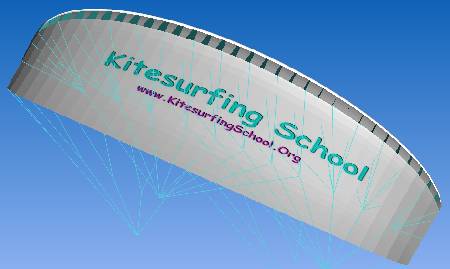
Il più popolare programma software per il progetto di aquiloni gonfiabili è SurfPlan (Surf sta per Surface = Superficie). SurfPlan è scaricabile al sito http://www.surfplan.com.au/. Il programma SurfPlan non ha ancora un manuale ufficiale. Comunque Kitesurfingschool.org ha uno "Pseudo" manuale dell'utente di Surfplan alla fine di questa pagina [se ci sarà abbastanza domanda, KitesurfingSchool.Org proverà, in futuro, a scrivere una versione completa del manuale SurfPlan - lasciatecelo sapere]. C'è anche un manuale in francese per un avecchia versione 3.4 di SurfPlan (dell'aprile 2005 e l'attuale versione di SurfPlan è la 4.5) su http://perso.wanadoo.fr/orveillon/manuel/manuel-1.htm.
I progettatori di foil potranno usare FoilMaker che era in giro prima di Surfplan ed è molto popolare tra gli entusiasti dei foil. FoilMaker può essere scaricato da http://www.foilmaker.co.uk/. FoilMaker ha un suo manuale dell'utente e il sito web mostra alcuni esempi di progettazione di aquiloni.
Esempi di progetto di aquiloni
E' meglio fare il proprio aquilone basandosi su un esistente esempio di progetto. Il miglior sito per gli esempi di progetto di aquilone gonfiabile è http://zeroprestige.org e anche specificatamente http://web.media.mit.edu/~saul/zeroprestige/kitemake/.
Il proprietario del sito web ha fatto un magnifico lavoro lavoro fornendo gli esempi di progetto di vari aquiloni da cui imparare per farsene. All'inizio, è consigliabile prendere in considerazione pochi parametri semplici come:
-
Colore
-
Dimensioni
-
Aspect Ratio (non cambiatelo molto)
Una volta che vi sentirete più a vostro agio con il software, leggete lo "Pseudo" manuale dell'utente di Surfplan e affrontare progetti più complessi come quelli di un foil, di un bordo d'attacco, il profilo di un bordo di uscita, ecc.
Per i foils, ci sono degli esempi di progetto sul sito http://www.foilmaker.co.uk/.
Raccolta dati di progetto di aquiloni della KitesurfingSchool.Org
Quindi progettate il vostro aquilone, fatelo (o fatelo fare da qualcuno per voi), provatelo e inviateci foto e commenti per futuri lettori della KitesurfingSchool.Org:
-
progetto di aquilone LEI a 2 linee baseto sulla teoria della sfera
-
progetto di aquilone LEI a 4 linee basato sulla teoria della sfera
(i file di estensione .sle sono da utilizzare con i programmi software citati)
Metodologia per la cucitura dell'aquilone
Uno dei migliori posti per apprendere come cucire un aquilone gonfiabile è il sito web http://zeroprestige.org/ e specialmente http://web.media.mit.edu/~saul/iap2003/howto/howto.htm. Il proprietario del sito fornisce una guida completa su tutte le fasi di lavorazione per cucire il vostro aquilone personale dall'inizio alla fine.
Il manuale di FoilMaker su http://www.foilmaker.co.uk/ ha una piccola sezione su come cucire i foil.
Se non siete abbastanza bravi per cucire il vostro aquilone, potete chiedere a qualcuno di costruire il vostro aquilone su misura o fornire uno dei vari progetti disponibili.
Kitesurfingschool.org ha fatto su misura il proprio aquilone gonfiabile e può fare adattamenti per produrre un aquilone gonfiabile secondo un vostro progetto (progetto di esempio o vostro progetto) ad un costo comparabile con quello dell'acquisto di un aquilone di produzione standard commerciale. Inviateci una e-mail (in inglese direttamente ad Hung Vu) se avete bisogno di assistenza in questo settore.
Gruppi di discussione dei costruttori di aquiloni
I due più popolari gruppi di discussione per i costruttori di aquiloni sono:
- Foildesign: http://groups.yahoo.com/group/Foildesign
- Inflatodesign: http://groups.yahoo.com/group/Inflatodesign
Unitevi a questi due gruppi, fate domande, usate il software, cucite un aquilone (o trovate qualcuno che vi costruisca il vostro aquilone su misura) e troverete che costruirsi un aquilone non è più un'arte così misteriosa.
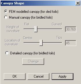
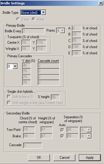
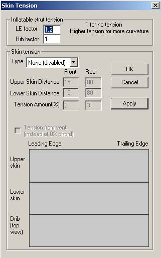
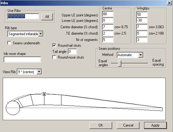
"Pseudo" manuale dell'utente del programma software Surfplan
[se ci sarà abbastanza domanda, KitesurfingSchool.Org proverà, in futuro, a scrivere una versione completa del manuale SurfPlan - lasciatecelo sapere]
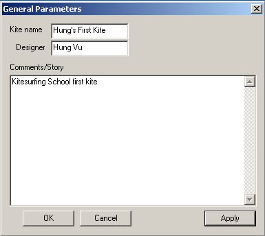
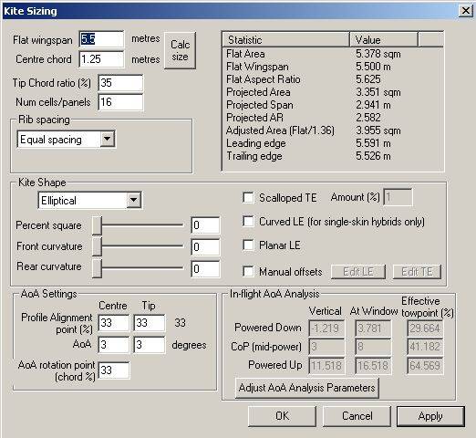
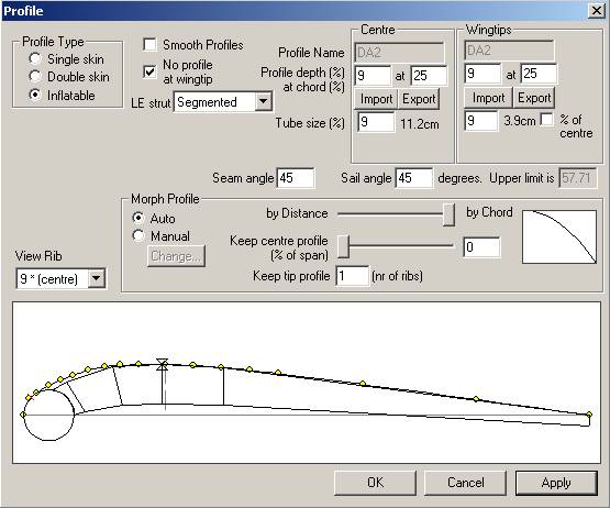
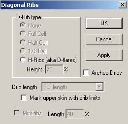
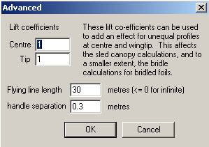
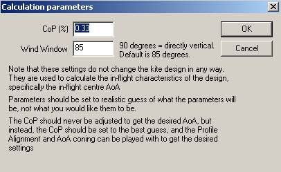
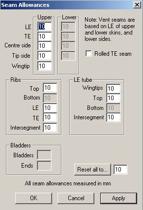
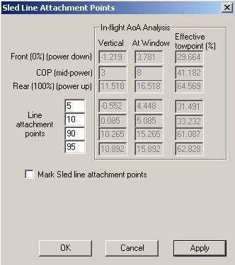
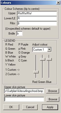
Surfplan, progettato e scritto da David Aberdeen, è un software molto semplice da usare ma fintanto che non ha un manuale, il suo ricco set di parametri può sopraffare il nuovo progettista di aquiloni (e anche un disegnatore di foil). Finche Surfplan sarà il più usato per progettare gli aquiloni LEI, in questo "Pseudo" Manuale dell'utilizzatore di Surfplan versione 4.5, vi forniamo la descrizione di tutti i principali parametri per progettare un aquilone con Surfplan (salteremo alcune parti dei foil come le briglie, ecc.). La descrizione dei parametri è post anello stesso ordine in cui compaiono nel menu EDIT di Surfplan:
|
Stelios Alexandrakis e Timo Elias hanno esposto un concetto interessante in merito alla peogettazione degli aquiloni LEI usando la teoria della sfera. Potete leggere di più sull ateoria all apagina web http://www.geocities.com/reystos/wipika/timostelios.html (può essere utile anche leggere il Brevetto di Bruno ed il Messaggio di Bruno al Kitesurf Group). Controllate anche la "Teoria della Sfera" nella sezione Files del gruppo della Inflatodesign su: http://groups.yahoo.com/group/Inflatodesign/files/ per poter avere maggiori informazioni.
Uno degli ostacoli per i nuovi progettisti di aquiloni è questa domanda "se cambio questo parametro, cosa cambio?". Il vantaggio della teoria di Stelios e Timo è che quando la capirete ed userete, tutti i parametri del programma Surplan saranno intercorrelati e potranno essere facilmente messi in sintonia:
-
Aspect Ratio (AR)
-
Rapporto etremità dell'ala/corda centrale (Wingtip/Center Chord Ratio)
-
Punto di allineamento del profilo (Profile Alignment Point (PAP))
-
Angolo di attacco del centro dell'ala (Center AoA (at vertical))
-
Angolo di attacco dell'estremità dell'ala (Wingtip AoA (at vertical))
-
Spessore del profilo centrale (Center Profile Thickness (in % della corda))
-
Spessore del profilo dell'estremità dell'ala (Wingtip Profile Thickness (in % della corda))
-
dimensione del bordo di attacco (LE tube size (in % della corda))
-
ecc.
Normalmente selezionate lo AR, il Rapporto etremità dell'ala/corda centrale ed il PAP (circa il 42% è richiesto dal brevetto di Bruno) dell'aquilone e poi calcolate tutto il resto con la teoria della sfera. Cliccate qui per usare la teoria della sfera che è basata su alcune formule e indicazioni che Stelios ha inviato nella sezione Files del gruppo di discussione InflatoDesign. Cliccate qui per i file .sle di Surfplan .sle per un 4 lineeprogetto di aquilone LEI a 4 linee basato sulla teoria della sfera. Alcune note sulla teoria della sfera:
-
Bruno attualmente ha specificato 0° di AoA tipico (a riposo) nel suo diagramma. La corda attraversa la base del tubo del bordo di attacco e la base del bordo di uscita. Lo AoA della teoria della sfera originale può essere usato per calcolare la dimensione del tubo. In Surfplan, la corda attraversa il centro del tubo del bordo di attacco e la base del bordo di uscita. Per questo lo AoA calcolato con Surfplan è 1/2 di quello della teoria della sfera originale.
-
Tutti i parametri ottenuti potrebbero non essere in assoluto i migliori per i moderni aquiloni LEI; comunque, sono ragionevoli e potranno funzionare.
Notate che la teoria della sfera era basata su un aquilone LEI 2 linee con il PAP al 42% (Bruno deve aver preso questo numero dalla "Hickhiker Guide to the Galaxy"). Questo progetto era necessario per un progettista nei giorni precedenti alla possibilità dell'uso di CAD per il progetto di aquiloni che che potevano essere bilanciati e guidati usando solo 2 linee attaccate all'estremità dell'ala (2 linee e nessuna briglia - questo era il sogno dei minimalisti). Con un moderno software di progetto di aquiloni a 4 linee LEI, il progettista e l'aquilonista hanno molte possibilità di controllo, pertanto la "risposta dell'universo" 42 non sarà più necessaria. Quindi usate la teoria della sfera come guida per progettare i vostri parametri. Siate avventurosi, con un aquilone LEI a 4 linee, le possibilità sono senza limiti .....
Messaggio di Bruno al gruppo di discussione Kitesurf Group
nel messaggio http://sports.groups.yahoo.com/group/kitesurf/message/17096 inviato al Kitesurf Group, Bruno menziona che uno può progettare un aquilone LEI semplicemente cambiando il parametro AR. Questo messaggio è stato il catalizzatore per Stelios per sviluppare la teoria della sfera per il progetto di un aquilone LEI.
|
From: Bruno Legaignoux <design@wipika.com> Date: Thu Aug 3, 2000 2:44 am Subject: Bruno Legaignoux's message
Hi,
I'm Bruno Legaignoux. For those which don't know my name, we are, with my brother Dominique the inventors of the inflated kite in the shape of a gore. This message is to try to put the numerous rumours off.
My brother and I were sailors (French Junior champions, cruising boat skippers, sailing instructors, surfers, windsurfers, etc...). We tried to develop very efficient sails and boats and finally we became interested in kites when seeing Jacob's Ladder, a catamaran pulled by Flexifoils, although we never flied a dual line kite. It was in 1984. After a few researches, we understood that no water relaunchable kite existed so it became obvious to us that we had to create one. You can see some old photos at www.wipika.com/Pages/chapitre1.html After one year of work, we were sailing with water skis and demonstrating the device during the 1985 Brest International Speed Week. We also applied for a patent. The project was to find one or several licensees within 2 years but windsurfing was at its acme and no windsurf company was interested.
We never stopped believing in this sport so we had 10 years of VERY HARD time, continuing the project without money, looking for new markets, for licensees, then creating our own company and producing in France in 1993-94... at a too high cost (please don't cry !)
Then Windsurfing declined and Kiteboarding time came. I am proud to see that we were the main actors of kiteboarding birth but for sure we were not alone. For example Cory Roeseler with the Kiteski device or Andreas Kuhn with a paraglider and a kind of wakeboard helped too with international media exposure.
In 1995-96 we went in very serious talks with Neil Pryde. Finally they renounced but they accepted to produce small quantities for us and we started selling these kites in July 1997 under Wipika brand mark. Then we found another manufacturer in Asia.
In 1998, Don Montague and Robby Naish came to us asking for a license. As it was our original goal, we agreed and told them that both of us needed a software to be able to make new designs quickly. I came to Hawaii and gave all my knowledge to Don Montague and their programmers. One year later, the program was working. We shared it. With it, everybody can make a new good kite in 30 seconds, just changing one parameter. For example, change AR = 2.5 (the default value) with 8 and you will appear as a genius designer!
WHY PATENT PROTECTION ? Some people hate this way. I think that when you are a well organized company in a market where products evolve very quickly, patent is just a waste of money and energy. But if you are a "small" independent inventor, you have no chance against large companies if you don't protect your ideas : they won't even give you just credit for that !
Who on this list is against intellectual property (music, literature, etc...) ? Our motivation was kept during the hard years because of the patent.
INFRINGERS Seen by my side, there are only 3 kinds of kites :
Obviously, I beat the infringers and already stopped a few ones. Something interesting to be known is that I have no obligation starting legal action immediately, that means that I can start even when they will have invested a lot of energy and money in their product. This is to explain that it is probably more risky for them to infringe that what they generally think.
NEW LICENSEES SOON ? Yes, we are open to give other licenses but to companies which are able to bring something to the market, not to companies with short term view or which sole way to get market shares is to discount their kites. In 2000-2001 a few high image companies will enter the market.
WHO INVENTED ? - who invented kiteboarding ? several people did it on their side without knowing that other people previously made something close. Ourselves we started in 1984 with windsurf boards because we were surfers and windsurfers but not waterskiers. We built several boards for that purpose. As our kites were very unstable at that time, we mainly used waterskis because the waterstart was easier, but the patent talks about windsurfing board type too. We also tested any kind of boats and many other "things" that you can't even imagine and a patent drawing shows a guy on two 40cm "water skates" (photos in the History page of www.wipika.com). We made and sailed them. It was fun. I 'm sure that we'll soon see advanced pilots trying this kind of skates.
- who "invented" high AR inflated kite ? In 1985 we made a 17m kite with aspect ratio 6 and with 100% double-skin (photos on Wipika web site... and a short video soon). With it, we waterskied with 6 to 12 knots of wind and, during the 1886 International Brest Speed Week, we were clocked at 14.5 knots (average speed during a 500m run) while the best world class windsurfers reached 10 knots. This is registered. We also made kites with 20%, 30%, 40%, 60%, 80%, 100% double skin, what was already described in the 1984 patent, and kites made of clear mylar with scrim. Probably you will see this kind of "improvement" in the next months or years.
- who "invented" inflated "struts" without inner tube ? a competitor ? No, in the past, we used 2 different construction methods for inflated struts : airtight fabric and mylar fabric with inner tube. These ways are described in the original patent.
- who invented 4 line straight bar with both front lines meeting at a "main line" going to the harness and with the bar sliding along the "main line" ? a competitor ? No, we own a patent on this device since 1995. I first used this device for buggying and won some races thanks to it. Seasmik uses without any license the exact device we described so we'll have to sue them.
- who invented 4 line inflated kite ? A competitor ? No, the above patent also describes how to settle inflated kites with 4 lines by cutting the edges for example (there are other ways). I always used "cut tip" kites with the 4 line straight bar. I explained all these things to Don Montague in 1998. Why didn't we apply these improvements earlier ? There are 2 main reasons :
Firstly, when you settle a company and you have no money, especially in France, you have to work 80 hours a week to have it working properly. So I had no time for R&D. It's why in 1999 I looked for people to take care of Wipika and get myself more time in R&D. I also moved in early 2000 to Dominican Republic which is really a perfect place for R&D.
Secondly, the market was not ready for more evolved kites. In the "early ages", we made very efficient kites then we understood that we had to make simple, stable and safe. In 1998, 100% of the users were beginners - there are not so many markets like this one ! In 1999, still 90% were beginners but the 10 other percents were starting to ask for more efficient kites so we prepared the Free Air AR3.3 range and started sales in early 2000. But because of Naish AR5 our new range is already old fashioned if you believe a few ones. My main concern is safety and when I hear that some beginners directly purchase AR5 kites, I'm scared. Firstly they are more difficult to relaunch but above all they are fast. That makes them dangerous for beginners in the state of the market (almost no schools nor well informed retailers...).
We are starting a competition to efficiency, just like windsurfing manufacturers did. Remember : "Hey guy, how many cambers do you have ? Only six ? ... and your board, what size ? 2.26m ? Too bad! mine is 2,195m !". Windsurfing is dying for this reason. And us, when ? A fact : the Wipika riders Franz Olry and Christopher Tasti, which actually win some events, don't want to use too high AR kites because they are so fast and unstable that they can't make the kind of tricks they do with more stable kites. They don't want a 20 kite quiver. They want simplicity. Same for Lou Wainman, Mauricio Abreu and some other ones. If you see them using high AR kites, it's because competition pushes in this way, not because they prefer (except in light winds). To resume, if we go too quickly, we'll burn our wings. All the people involved in kiteboarding should take care with that.
R&D AGREEMENT WITH NAISH ? Any kind of commercial/strategical agreement was never made. Both companies are completely independent/free of mutual contract. Both are Legaignoux licensees with same contract terms.
4 LINE KITES Wipika supplies the Classic kites since July 1997 with an additional webbing so that all the Classic can be settled with 4 lines. That means that we believe to the 4 line use since a long while but 99% of the customers didn't want to hear about it last year. There are several ways to settle your Classic as a 4 line kite, I'll come back on this matter in another message. Very soon, the Classic kites will be sold with a second webbing, like the Free Air, to simplify transformation. Classic and Free Air will also receive long velcros to fold the tips. Many new Wipika items will be available in the next weeks and months, including an interesting 4 line bar. We'll keep you informed. You are welcome to use abstracts of this message for public use as long as it is in good faith. Please don't expect that I'll react to the messages which could follow mine, I'm still too busy to do it. Sorry!
Thank you for your time and... Best winds to all of you,
Bruno |
Peter Lynn's Myths on Kitesurf Group
Peter Lynn's Myths posted on the Kitesurf group by Ian Young at http://sports.groups.yahoo.com/group/kitesurf/message/17055.
[When Peter released these myths, it created many controversial debates and one of the reasons was that it's not clear what Peter meant by "angle of attack". Note that Peter talked about kite design here so the "angle of attack" he referred to probably meant "built-in AoA" and not the AoA of the kite when flying]
Date: Thu Aug 3, 2000 7:34 pm
Subject: Peter Lynn's Six Aerodynamic Myths of Kite Traction I
newsletter ...
The Six Aerodynamic Myths of Kite Traction.
Myth One.
That the upwind performance (that is, lift/drag ratio) of kites is primarily
a function of profile and aspect ratio.
Wrong. The strongest determinant of L/D is angle of attack. Low angles of
attack yield high L/D in an inverse relationship, profile and aspect ratio
have comparatively little effect.
Myth Two.
That the Lift Coefficient (power for size) of a kite is primarily determined
by it's profile and aspect ratio.
Wrong. Angle of attack is again by far the strongest determinant of pull
for area, and by close to a direct linear relationship in the range that
matters for kites.
Myth Three.
That high aspect ratio equates to high performance.
Correct in theory but misleading for kites in practice. Aspect ratio
(defined as span squared divided by area) is a strong determinant of induced
drag, the dominant form of drag at low speeds for efficient airfoils- but
kites are not efficient airfoils by any definition, so aspect ratio
determined induced drag is not the major drag component for kites. It would
be possible to make a square wing (A.R=1.0) that is more efficient than the
highest aspect ratio high performance kite currently available- (but making
it useable as a kite would be another matter).
Myth Four
That Thin sections are "better" than fat sections.
Wrong. Unless your kite is to fly at something approaching the speed of
sound anyway. Sections as fat as 16% (maximum thickness as a proportion of
chord) lose nothing by L/D or lift coeff. to thinner sections up to 300km/hr
or so and are less prone to stalling and luffing.
Myth Five.
That double skin wings (ie three dimensional airfoils) are more powerful
than cambered single skin wings.
Wrong. Cambered single skin wings will generally have higher lift
coefficients than fully shaped 3 dimensional wings because they can work at
higher angles of attack without stalling. 3 D forms will be more luff
resistant and can have higher L/D but they won't be more powerful.
Tanstafl. (There ain't no such thing as a free lunch.)
The fundamental design conflict is between one and two above. Traction
kites require high angle of attack to have desirable power for size
characteristics but low angle of attack for good upwind performance.
Some kitesurfing tips:
*Early this year we added an extra valve near the wingtips on Arcs to speed
their inflation and to make them more resistant to tip collapse in the case
that inflation leaks develop. We aren't sure that this was necessary but
added them just in case. Being near the tips, the disadvantage of these
extra valves is that they can ingest water during relaunching. If this is
a problem for you just seal them off internally with double sided tape- they
can then easily be reopened if ever necessary. Thank you to Nick Grant for
this.
*If you're going to break things, it is not a good idea to do so when
against wind and tide and far from land. In Tahiti last week Mike Holland
broke a line in such circumstances and was unable to re-rig, and relaunch so
spent one day of his South Pacific holiday swimming in. Thank you Mike for
this tip.
*When you are using our wrist leash velcro'd to the bar end so that it
doesn't get twisted up in spins, lash it on with knitting wool in addition
to the velcro so that it doesn't come off prematurely but will still release
when required- just like wool ties on a yacht spinnaker. Thank the sheep
for this one.
New things this month- Nothing!, Which is the first time ever, except that
there is something but I'm just not talking about it until we hear back from
our travelling testers. It was what Mike was testing in Tahiti when he had
a line break and the long swim.
And a little gossip to round off: Andy Reid; windsurfer, kitesurfer,
boardmaker and (with Justin), our kite test rig operator, finishes his B
Eng. this year and goes to work at Team New Zealand for the next defence of
the America's Cup. Our loss, their gain- congratulations Andy.
Peter Lynn, Ashburton New Zealand, July 31, 2000.
Cheers,
Ian Young
Il titolare, l'amministratore, l'autore e tutti coloro che hanno collaborato a questo sito non rappresentano nessuna garanzia riguardo ad errori, omissioni o incorrettezze delle informazioni contenute in questo sito web. Usare le informazioni quì contenute a proprio rischio e pericolo. Il titolare, l'amministratore, l'autore e tutti coloro che hanno collaborato a questo sito non sono responsabili per perdite o incidenti a voi o a terzi incluse le perdite di affari, le perdite di materiali, attrezzature o danni alle proprietà, lesioni o morte derivante da voi o terzi che utilizzano le informazioni quì contenute.