Advanced Signal Flow Part 1
Dateline: 12/16/97
Different Ways to The Same Places
The features of the console series put together the nuts and bolts of the console and how to work quickly to get the desired goal accomplished. Here are some advanced tricks you can use to get around and through the console in other ways.
The Versatile Channel Fader
Most inline consoles will let you use
the small fader in two ways during mixdown. Normally the small fader (channel
fader) is after the mic pre-amp and before the multi-track buss. The
mic must pass through here on it's way to the multi-track. However, during
mixdown this fader can often be used as an additional monitor fader. For
instance, you could assign it line input status (most consoles will let
you toggle the channel fader from mic to line) and then route additional
tape returns or reverb returns into it. Once you patch these returns you
simply assign it to the stereo buss with all the other mix faders. How
this stereo buss assignment happens
varies from console to console. Some
manufacturers give you the option of routing to the multi-track busses
or the Stereo buss via a button. This is the most flexible of options because
you can configure the fader as a monitor or channel fader easily. However
all is not lost if this is not available. Remember that this fader still
routes to the multi-track buss. If you patch a few multi-track busses into
a few monitor faders, then assign the channel faders to those busses you
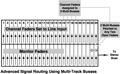
can take the back door to the stereo buss. (see the diagram below).
It's important to use this subgrouping
function in groups of two odd/even busses. These will be patched to your
two monitor faders and hard panned left and right. This way you can assign
your channel faders to these two multi-busses and your panning will be
reflected in the Stereo buss. For instance, patch buss 1 and 2 to two open
faders. Pan these faders hard left and right. Now patch a line input into
your channel fader and in turn assign it to buss 1/2 and pan it like you'd
want to hear it in the stereo buss. Make sure your monitor faders are not
muted. You should now be hearing your channel fader's signal in the stereo
buss and the channel pan should reflect what you're hearing.
Advanced Signal Flow Part 2
Dateline: 12/30/97
Subgrouping Instruments
Last week we discovered how to route the channel fader to the stereo buss using the multi-track busses. This allows you to use the channel fader as an additional line return for more tape tracks or reverb returns. Now let's talk about the advantages of subgrouping groups of instruments for use during mixdown.
When I mix I like to start with things laid out in groups on the console. For instance, I'll cross-patch the drums and percussion so they're together, then groups of keyboards then guitars and background vocals. I'll leave a spot free with a few faders open for the lead vocals and automated reverb sends right in the center of the console. This way when I'm ready to make my vocal moves in the mix, my head is right between both speakers. This is optimum for being able to hear nuance of levels or other things that might mask your vocal.
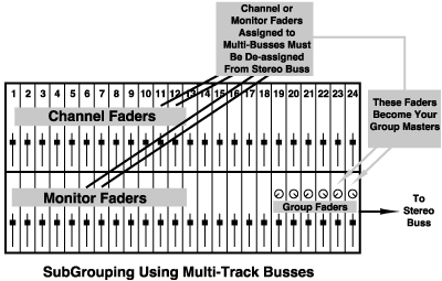
Once I've got all my patching, levels, EQ and other things all setup, I'll subgroup certain instruments together. This does not negate you're individual control of level but enables you to make master group moves with backgrounds, drums, percussion etc if you need to. For instance I'll group the drum kit to two faders (or a stereo fader if it's available), keyboards to another and guitars to another (all in stereo if that's my plan). Then it's easy to make master group moves with or without automation.
How to Get There
Of course each console is different and may have grouping functions that you can easily implement. (for instance SSL has dedicated stereo group faders that are easily assignable). It's much the same as we did with the channel fader in last weeks feature. (I'm taking for granted that the console we're working with does not have a grouping function and will allow you to send the monitor fader to the multi-busses). First designate a gang of faders that you can use as group masters. These should be easily reachable so when you make your moves you're not off-axis from the speakers center image. Patch an odd even multi-track buss out combo to two faders and label it GROUP 1 (or with the name of the instruments you're grouping, drumkit for instance). This patch might look like multi-track buss outs to Console line inputs. Then patch another two busses to another two faders etc... as many as you need. Then assign these subgroup master faders to the stereo buss. Now simply take the groups of tape returns you wish to group, de-assign them from the stereo buss and re-assign them to your group faders via the multi-track busses that you chose. The odd/even buss assignment should follow your monitor pan (that depends on the console) and should be in the same stereo perspective as your original channels. Provided of course that your group faders are panned hard left and right (don't forget that or you're mix will be in mono). See the diagram below to further visualize what's going on.
ReCap
Now you can see how you can control your
mix ingredients both individually and in groups. It's really the best of
all mix setups because it gives you a lot of control. For instance if you
want to fade groups of instruments in or out as part of the mix building
process you can do it easily.
Advanced Signal Flow Part 3
Dateline: 1/6/98
Endless Auxes
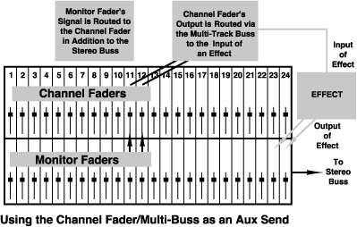
Console manufacturers with flexibility in mind will let you source the channel fader's input from the monitor fader of the same I/O. This simply means that the fader which you are listening to in the stereo buss also goes to the channel fader and stops there. We know by now that the channel fader can usually be assigned to the stereo buss or the multi-track buss (on most inline consoles). Since we're through recording we don't need the multi-track busses to go to the tape machine, so we can use those same busses to go other places.
Sending the Multi-Track Busses Elsewhere
The beauty of a patch bay is the ability to send line level signal anywhere. In this case we're going to patch an output of a multi-track buss to the input of a reverb or other effect. You can now see that the channel fader is just another post-fader send that travels via the multi-track buss to an effect. This way you can use the channel fader as a volume control just as you would an aux send. In one case you patch the output of the aux send master to the input of an effect, in the case of the channel fader you assign the output of a chosen multi-track buss to the effect.
How to Make it Work For You
Here's the working scenario. You use up all your aux sends and need an additional send for a particular reverb. You'd patch the output of buss 1 (this can be any buss but for our demo it's buss 1), to the input of an effect. You then bring back the output of the effect to two free inputs on the console and send those to the stereo buss. Let's say for our purpose we want to use this effect on some background vocals and guitar. You'd then assign the input of the channel faders on the background and guitar I/Os from the monitor fader. You're channel fader is now getting a post-fader feed from the monitor fader of the same console I/O. You then assign the channel fader to buss 1 and it becomes a master (post-fader) volume control that sends to your reverb. See the diagram below to further illustrate this:
Flexibility
As you can see, there are a lot of very
cool ways to route signal on or about the console. Stay tuned here for
more of the same.
Advanced Signal Flow Part 4
Dateline: 1/13/98
Direct Outputs
Direct outs are an alternate way to get
your signal from the channel fader to the multi-track tape machine. You
already know that the multi-track buss is a way to send individual and
groups of signals to one or more tracks. If you're signal-to-track relationship
is one-to-one, using a direct output is a cleaner way to get your signal
from the console to the multi-track. You're not even limited to going to
the same number track as the I/O you're using. If the direct output is
represented on the patch bay you can assign it on the individual I/O and
then patch it to any track you like (or plug directly from the console
to the tape machine if you need to).
You just have to remember that you can't
mix two signals using direct outs, it's strictly one signal to one track.
Knowing Your Path
When you use the multi-track buss you're going through yet another amp on the console. This ads noise and is another gain stage to manage. When you use a direct out you eliminate another gain stage. The more gain stages you can eliminate in your signal path the cleaner your signal will be. Let's explore for a second just how many gain stages are in a single I/O on a console. A gain stage is every time you have the opportunity to ad gain, and noise. If your console has 4 bands of EQ and 4 Aux sends, that's 8 chances to ad gain right there. Add the mic preamp, channel fader, monitor fader, multi-track buss, stereo buss (summing amp) and line trim you have a total of 14 chances to mismanage your gain structure.
Keeping Your Signal Clean
When you're tracking and mixing, having
gain stages working efficiently with each other and other amps outside
the console should be a big part of your focus. For instance if you're
barely sending signal out through an auxiliary to a reverb and you must
boost the gain of the output in order to hear the effect, you're adding
unnecessary noise. It would be better to hit the input of the reverb harder
by boosting the aux send to the effect and downplay the noisy output stage
of the effect.
Advanced Signal Flow Part 5
Dateline: 1/20/98
Keeping it Clean
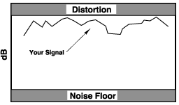
Every audio device, be it a fader, line trim, auxiliary send, or audio tape has what's called a noise floor. This is the inherent noise of a device. It might seem that digital recorders have no noise but in actuality they just have a very low noise floor. So everyone's in the same noisy club. Along this noisy pathway comes your signal. Every opportunity to add gain along this pathway is an opportunity to add noise to your once pristine track. It's inevitable that some noise will creep along but if you manage the gain properly this will be masked or greatly understated by the fact that your signal is printed nice and strong.
The Box
I like to think of recording as fitting the signal in a box. At the bottom of the box is the noise floor. At the top is distortion. The closer you can get your signal to distortion without going over, the cleaner it will be. This is because you're away from the dreaded noise floor.
As we said the more opportunities you have to add gain, the more you can degrade your signal. There is a concept at your disposal that can greatly help you along your signal path. It's called.......
Unity Gain
Unity gain is the point at which you're neither adding or subtracting level from your signal. This of course means that you have to have the means to add gain, namely a volume control. This could be a fader or a volume pot. Unity gain is usually marked as ZERO on the fader or pot. Some pots have no scale but are detented. This is a notch you can feel when you turn the knob. This detent is sometimes zero. However, some manufacturers choose to keep us all in the dark. If the manual for the device doesn't give you a clue, I usually guess that unity is about the 2 O'clock position, or number 7 on a one to ten scale.
Let's trace a bit of our signal from mic to multi-track and see how we can use unity gain to keep our signal cleaner. The signal will flow as follows:
Mic
Mic Preamp
Channel Fader
Multi-track
Buss
Multi-track
machine
There are three opportunities to add gain here. The mic pre, channel fader and buss trim. There are amps in all three of these gain stages, all with noise floors and distortion. Think of the box. The best possible scenario would be to eliminate two of the three by using the unity gain concept, then using only one as a master volume. In this case the mic pre is the best choice for the master volume. Therefore, you'd set your channel fader and buss trim at ZERO and not add any gain there. Then you'd use the mic pre as the volume control that adjusts your level to tape.
Next week we'll continue along the signal
path and explore how to keep our signal clean as we go.
Advanced Signal Flow Part 6
Dateline: 1/27/98
Keeping it Clean - The Tape Return
Getting your signal clean to tape is only half the battle. To mix properly and get the most out of your console you need to manage your gain all the way to your speakers and two-track tape machine. Getting in the habit of doing this time and time again is to your benefit.
Let's trace our path from the tape machine to the speakers and two-track. When the signal enters the console the first thing it usually sees is the line trim. This is another amp you encounter before the monitor fader. From the line trim you go through the auxiliary sends and EQ stages and then to the fader. In order to hear all the faders on the board they must spill into the summing amp. This amp sums all the different faders to stereo, and then they're routed to the various two-tracks and speakers in the room. To get to the summing amp the faders travel along the Stereo Buss. A buss is a common signal line. On some consoles the monitor faders normally go to the stereo buss. On others you must assign the fader to the stereo buss. There is then a master control called a Stereo Buss Master Fader. It's usually set aside and is a different color to tell it apart from the other faders. So here's the breakdown of signal flow from tape:
Multi-track
Line Trim (console
input section)
Monitor Fader
Stereo Buss
Stereo Buss
Master Fader
Speakers/Two-track
More About Unity Gain
Last week we talked about eliminating one or more gain stages by setting them to unity gain. There are three gain stages in our example above. To properly manage the gain on the tape return path you should set your line trim and your Stereo Buss Master to unity gain (unity gain on the stereo buss master fader is marked as zero, see your manual for unity gain on your line trim). Then use your individual faders to adjust volume on the console. Your goal is to "fill up" the stereo buss and not overload it. How you gage this is to watch your stereo buss meters as you mix. Your goal is to use up the headroom in the stereo buss and thus stay away from the noise floor .
No-Nos
What you don't want to do for instance
is over-do it on your monitor faders and then adjust your Stereo buss master
level down 5 dB or so. This is not smart gain management. You're adding
noise at the monitor fader and not utilizing your headroom at the buss
master. Keeping all these gain structures in a row will keep your tracks
sounding clean by minimizing console noise.
Advanced Signal Flow Part 7
Dateline: 2/3/98
Clean Effects Sends
Auxiliaries are most often used for headphone
mixes and parallel effects
devices. Because of the abundance of gain stages when using effects,
we'll concentrate on that side of the auxiliaries' dual personality.
First let's count the number of gain
stages that your signal will encounter in route from the auxiliary and
back again:
Auxiliary Send
(individual sends on each I/O)
Auxiliary Master
The Effect's
Input Setting
Any Internal
Level Setting the Effect May Have (software)
Output Setting
Console Fader
(return level)
There are six opportunities to add gain at these stages. We know from past features that the best way to manage gain is to employ the concept of Unity Gain for the stages that aren't directly being used to manipulate gain. In this case the individual auxiliary send and return fader will be the way we manipulate gain directly to and from the reverb. All others will be set to an optimum setting.
The Game Plan
Before we get to the individual settings let's discuss some theory here. The problem with effects is that they create a lot of noise in the process of effecting the signal. This is why we use them in a parallel fashion as opposed to plugging our signal directly through them. If we did plug through them, we'd be at the mercy of the device as far as regulating our noise level as opposed to signal level. This is called Signal to Noise Ratio. The greater the ratio the happier we are as engineers. So, the basic plan is to hit the unit hard at the input, (without overloading it of course) and then turn down the output to keep the noise at bay.
Just Doing It
Aux Send
The individual send is used to set the
level to the effect. The thing to watch when you're sending the signal
to the effect is the input meter of the effect.
Hit it hard but not too hard, leave
yourself some headroom
for other signals you may send later in the mix.
Aux Master and Effect Input
The aux master should be set to unity
which is usually about 7 or 3/4 the way up on your rotary pot. The effect's
input setting should also be unity.
This is tricky because most manufacturers
don't give you a clue. Once again I err on the side of caution and use
the "7 or 3/4 way up" rule that we mentioned a moment ago.
Internal Level
Next, page through your editable parameters for any software based level settings in your effect. It depends on how this sounds when you do it, but I usually boost it a bit and see what happens. Listen to your outputs and if there's too much noise added then back off. For instance, on the Lexicon PCM70 and 80, I go in and crank the software level of the individual effect and it works great. Be careful but see what you can get away with.
Effect Output
Output settings can be a dedicated knob or not exist at all, it depends on the unit. On the Ensoniq DP-4 there is a dedicated input and output knob. Once again experiment. The output might be an attenuator and in that case should be wide open. Reading the manuals or questioning the manufacturer via email or a support line would really help here and I highly recommend it.
Return Settings
Your return level then becomes your savior because you can ride them down in the mix and bring the noise floor way down. This stage should not be run at unity for that reason.
ReCap
Advanced Signal Flow Part 8
Dateline: 2/10/98
So Far So Good
The underlying theme of a lot of advanced signal flow is to find the cleanest path for your signal from here to there and back again. The studio is loaded with gain stages where you can get yourself into noise trouble. By using the concepts of Unity Gain or bypassing these stages all together, you can make good choices that will help keep your signal strong and clean.
It All Adds Up
I once heard a comment that someone had "Checked a buss output and a direct output against each other one-to-one, and noticed no difference in noise".My answer to that is, yes, one-to-one the noise is not that big of a deal but if you add up the outputs of 20 busses then you'll see the difference. This idea really underlies a lot of the decisions I make along the way as I'm doing a session. There are a lot of small steps you'll take along the way but the sum of all the small steps in the end is better quality audio.
Re-Thinking Inserts
As we've seen, an insert is a courtesy in and out point provided for use with serial devices. It's a simple out and in point provided out of each I/O and represented at the patch bay. In the case of smaller studio set-ups it would be at the back of the console. Inserts can be balanced or unbalanced, depending on the console. For instance, some of the Mackie console use a balanced connector (TRS 1/4") to make an insert that only uses one receptacle. This saves space and money. This is not a balanced connection but uses the tip and ring as either in or out and the sleeve as ground. The other end of the cable of course would have to terminate to two separate plugs that you could plug into separate in/out connectors on the piece of gear you're inserting.
Another Use For An Insert
Sometimes when I'm doing a mix session I will bring my tape returns back through the insert returns on the console to bypass the line amps. This goes back to my "small steps" comment earlier. If you can bypass 20 or more line amps then you're helping your signal quite a bit. In the process of doing this you might lose some other console functions like soloing or what-not. But if you have a problem with overloading your line amps at the input or the console just plain sounds better when returning tape through the inserts, then by all means do it.
Inserts Built-Into Outboard Gear
I own a couple of Calrec Mic pre-amps that Brent Averill refurbished. They are really cool because they come with a preamp and EQ and an insert all in one rack space. I learned from Brent that you can use the EQ section independently of the mic pre by inputting signal into the insert return and then using the output as the main out. You can also split the unit and use the input and insert send as another in and out point for signal. So you can take one unit and use it for two discrete signals by simply using the insert as another way to get in and out of the unit.
Re-Cap
What this all boils down to is that there are many roads to Oz. The more intuitive and smart you can become by trying all means and experimenting to eliminate noise from your path, the better engineer you will be. It's all experience and the more I get into this business the more I realize what I DON'T know. I'm learning every day just like you are and that's what I love about it. It never gets old. There's always some new piece of gear to learn or a new technology to explore.